Laser shaft alignment - our passion your precision
We care about your assets - Alignment is our business

PRUFTECHNIK, the inventor of laser shaft alignment, has decades of experience in developing, manufacturing and applying laser-based alignment measurement systems.We offer a full range of shaft alignment products.
All our devices have a modular design in order to meet the exact needs of our customers. They are also available in intrinsically safe versions for use in hazardous areas. Our measurement systems are used worldwide in many alignment applications of rotating machinery in most industries.
Precision alignment pays back
Eleminate misalignment
Rotating machinery is susceptible to misalignment. Machines that are well aligned at the commissioning stage and thereafter regularly maintained, will in the long term reduce both plant operating and maintenance costs.
Laser precision alignment extends machine availability as the Mean Time Between Failure (MTBF) increases.
It protects assets and increases product quality, as vibration is reduced to very low levels.
When misaligned, the loading of the shafts dramatically increases due to the reaction forces created within the coupling.
Key benefits of shaft alignment
Effects on power consumption

Significant power savings can be made through accurate alignment. Precise alignment eliminates reaction forces and reduces energy consumption by up to 10%.
Reduced repair incidences

Mechanical seal repairs decline by up to 65% when precision alignment is carried out on a regular basis.
The rate of repairs declines by up to 30% when precision laser alignment becomes an integral part of the pump repair schedule. Maintenance costs are also reduced through lower parts expense and inventory levels.
Longer machine life

The smaller the offset misalignment, the higher the expected bearing life cycle.
Traditional shaft alignment methods
Conventional measurement methods possess a low resolution for the adjustment of modern machinery. The straight edge/feeler gauge methods depend on the limited resolution of the human eye. The resulting resolution of 1/10 mm is for most machinery inadequate.
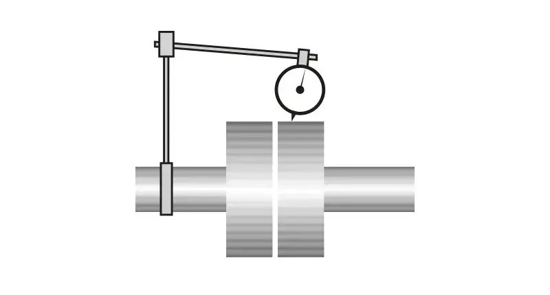
Sagging indicator brackets

Sag should always be measured before actual alignment readings are taken irrespective of how solid the bracket appears.
Low resolution

Up to 0.005 mm rounding error may occur with each reading – which easily results in an error of up to 0.04 mm in the calculated results.
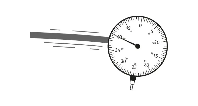
Sticking/jumping dial hands

Sometimes the indicator must be tapped in order for the needle to settle on its final value.
Dial indicators normally have a resolution of 1/100 mm, but calculations tend to be complicated, requiring highly experienced users, and jobs take longer to accomplish. These methods are prone to human influences when reading dial indicator values or computing the alignment condition.
Play in mechanical linkages

Slight amounts of looseness may not be noticed, yet produce large errors in results.
Reading errors

Human errors occur all too often when dials must be read under cramped, poorly-lit conditions and severe time constraints.
Tilted dial indicator

The indicator may not be mounted perpendicular to the measurement surface so that part of the displacement reading is lost.
Axial shaft play

This can affect face readings taken to measure angularity unless two axially mounted indicators are used.

 PRÜFTECHNIK NDT GmbH


